SF32LB52-DevKit-ULP
Overview
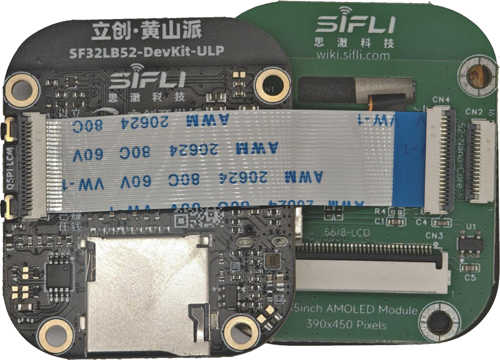
The SF32LB52-DevKit-ULP is also known as 立创黄山派, LCKFB-HSPI-SF32LB52-ULP, and SF32LB52-ULP. It is a compact ultra-low-power wearable development board built around the SF32LB52x family, positioned as a smartwatch and fitness-band prototype platform rather than a simple MCU breakout board.
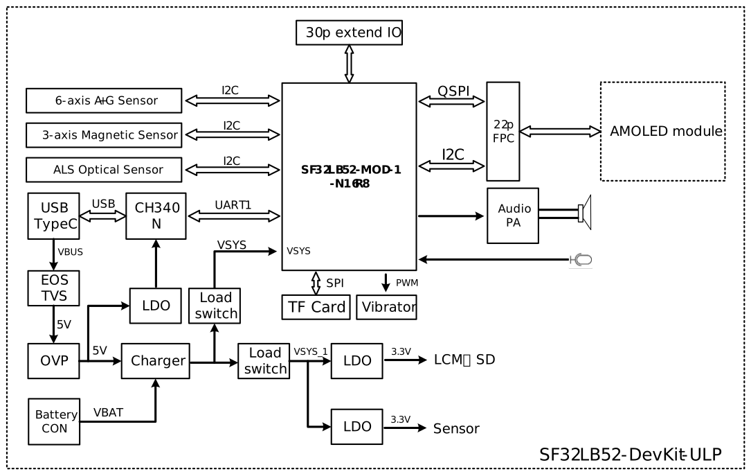
Compared with the LCD, Nano, and Core-3p3 boards, this board is more product-like: it combines an SF32LB52 module, AMOLED display, touch, microphone, speaker amplifier, RGB LED, vibration motor drive, motion sensor, magnetic sensor, ambient-light sensor, battery charging, and power-measurement jumpers. That makes it especially useful when the product question is not just "does the MCU run?" but "how does the whole wearable system behave on battery?"
SiFli's ULP board guide remains a placeholder. For the detailed board configuration, use SiFli's Chinese Huangshan Pi development-board guide, which documents board V1.0.0; its component values below are the baseline for that revision. The separate LCKFB hardware wiki does not identify its board revision and lists several different component numbers. Treat those as a possible revision/source mismatch, not interchangeable parts, and verify the actual board markings, schematic, and BOM before design work.
Release-status caveat: SiFli's V1.0.0 guide says the documented board was then for internal trial and would be revised before external release. This statement is specific to that source revision; it does not establish the status or BOM of later boards. Verify the exact board revision and BOM.
The SiFli SDK board page lists this board target as sf32lb52-lchspi-ulp. The SDK board page and the package-contents section of the Chinese Huangshan Pi guide use SF32LB52X-MOD-1-N16R8, while the SiFli module model guide and the GPIO-table caption use SF32LB52-MOD-1-N16R8. The sources do not explain this X difference. The SDK target is clear; verify the fitted module's marking and BOM rather than inferring that the two SKU spellings identify different hardware.
Naming
| Name | Where It Is Used |
|---|---|
| SF32LB52-DevKit-ULP | SiFli/OpenSiFli board-family naming |
| SF32LB52-ULP | Short hardware/product name |
| LCKFB-HSPI-SF32LB52-ULP | LCKFB project/order naming |
| 立创黄山派 / 立创・黄山派 SF32LB52 | Chinese product and documentation name |
Use these names as aliases for the same board family when searching for hardware documents, examples, purchase pages, or community material. For schematic, pinout, or BOM work, always confirm the exact board revision and vendor document set.
Board Highlights
- SF32LB52-MOD-1-N16R8 module based on SF32LB52x
- SF32LB525UC6 standard module configuration
- 8MB OPI-PSRAM, 144MHz interface
- 128Mb QSPI-NOR Flash, 72MHz STR mode
- 48MHz main crystal and 32.768kHz RTC crystal
- On-board PCBA antenna
- 1.85-inch AMOLED display, 390 x 450 resolution
- Quad-SPI display interface with touch support
- On-board MEMS microphone
- Analog audio output with Class-D speaker amplifier
- External speaker connector for 3W/4ohm or 2W/8ohm speakers
- USB Type-C UART interface through CH340N for download, debug, and power
- USB2.0 FS signals exposed through the 30-pin expansion connector
- MicroSD card slot using SPI
- One function key and one power/reset key
- SK6812MINI-HS RGB LED (SiFli Huangshan Pi V1.0.0 guide; the unversioned LCKFB page lists WS2812B-2020)
- Vibration motor driver circuit with external motor solder pads
- LSM6DS3TR-C 6-axis IMU
- MMC5603NJ 3-axis magnetic sensor
- LTR-303ALS-01 ambient-light sensor
- Battery charger and power-management devices for wearable power testing
- 2x15-pin, 1.27mm-pitch expansion header with GPIO and current-measurement support
When to Use This Board
Choose SF32LB52-DevKit-ULP / 立创黄山派 when the goal is wearable system validation.
- Build watch, band, and sensor-rich wearable prototypes
- Evaluate AMOLED UI behavior on the SF32LB52x platform
- Test touch, motion sensing, magnetic sensing, ambient-light sensing, audio, vibration, and RGB LED behavior together
- Measure battery, system, and 3.3V current paths during sleep and active use
- Validate wake-up flows driven by buttons, sensors, touch, or firmware timers
- Compare real product-like power behavior against early estimates from simpler DevKit boards
For a display-focused general evaluation board, use SF32LB52-DevKit-LCD. For compact solder-down module prototyping, use SF32LB52-DevKit-Nano. For maximum direct pin access during early bench bring-up, use SF32LB52-DevKit-Core-3p3.
Hardware Configuration
| Area | Configuration |
|---|---|
| Core module | SF32LB52-MOD-1-N16R8 |
| MCU | SF32LB525UC6 |
| PSRAM | 8MB OPI-PSRAM, 144MHz interface |
| Flash | 128Mb QSPI-NOR Flash, 72MHz STR mode |
| Display | 1.85-inch AMOLED (ZC-A1D85W-010), 390 x 450, 800 cd/m², Quad-SPI |
| Display driver | CO5300AF-01 |
| Display power IC | BV6802W |
| Touch controller | FT6146-M00 |
| Microphone | On-board MEMS microphone |
| Speaker output | Class-D amplifier, external GH-1.25mm speaker connector |
| Storage | MicroSD card over SPI |
| Motion sensor | LSM6DS3TR-C 6-axis IMU |
| Magnetic sensor | MMC5603NJ 3-axis magnetometer |
| Ambient-light sensor | LTR-303ALS-01 |
| USB-UART | CH340N over USB Type-C |
| Battery | External Li-ion battery through GH1.25mm connector |
| Charger | SY6103, maximum charge voltage 4.5 V; default 450 mA constant-current setting; maximum current 500 mA |
| Protection/power devices | SY5320 OVP, LP5240HVF load switch, ETA5055V330DS2F LDO |
Revision-dependent component list — verify before design: SiFli's V1.0.0 Huangshan Pi guide lists SY6103 charger, SY5320 OVP, and SK6812MINI-HS RGB LED. The unversioned LCKFB hardware wiki instead lists AW32001ECSR in its feature list and AW23001ECSR in its charging section, plus LP5305AQVF OVP and WS2812B-2020 RGB LED. The sources do not establish whether these differences reflect a hardware revision or stale documentation. Use the SiFli V1.0.0 values only for that documented baseline; verify the actual board markings, schematic, and BOM before relying on component-specific behavior.
Package Contents
The Huangshan Pi board set is documented as including:
- Core board
- Screen board
- Battery
- Speaker
Verify the purchased kit contents before planning a lab setup, because accessory bundles may differ by seller or production batch.
Power and Battery
The board supports two primary power modes:
- USB Type-C power
- Standalone battery power
The battery input is intended for a single-cell Li-ion battery using a GH1.25mm connector with forward pin order. The documented charging configuration supports a maximum charge current of 500mA, with a default constant-current setting of 450mA.
When using the board without a battery and supplying VBAT from a bench supply, the documented VBAT input range is 3.7V to 4.7V, with 3.8V recommended for normal-voltage supply testing. The SF32LB52-MOD-1-N16R8 power thresholds are documented as 3.58V for power-on and 3.48V for power-off.
The LCKFB hardware guide warns that the long-press key function may not work when no battery is connected. Verify this behavior on the exact board revision and intended power setup.
Power Measurement Jumpers
The board exposes current-measurement jumpers for the major power paths.
| Pins | Path | Purpose |
|---|---|---|
| 5-6 | VBAT path | Insert a current meter between battery/charger and downstream system |
| 7-8 | VSYS path | Insert a current meter in the VSYS path |
| 11-12 | VCC_3V3 path | Insert a current meter in the 3.3V main rail |
For normal operation, pins 5-6, 7-8, and 11-12 must be shorted with jumpers. Remove the appropriate jumper only when inserting a current meter or power analyzer.
Download and Debug
Use the USB Type-C UART interface for firmware download, serial logs, and board power during normal development.
Required hardware for first bring-up:
- SF32LB52-DevKit-ULP / 立创黄山派 board
- USB 2.0 data cable
- Host computer running Windows, Linux, or macOS
Optional hardware:
- External speaker
- TF card
- Li-ion battery, 450mAh or larger
- Second USB cable when UART debug and native USB testing are needed at the same time
Use a real data-capable USB cable. Charge-only cables can power the board but will not expose the serial data interface.
SDK Build Targets
SiFli's SDK uses the exact board-target name sf32lb52-lchspi-ulp with scons --board=<board_name>. This is an SDK build-target identifier, not necessarily the product name printed on a board or module. Confirm the target against the Supported Boards index and the SDK's build_config_gcc.yaml for the SDK revision in use.
Key Signal Assignments
| Signal | Function |
|---|---|
| PA44 | VBUS_DET, charger insertion detect |
| PA43 | KEY2 |
| PA42 | Audio_PA_EN |
| PA41 | Touch interrupt |
| PA40 / PA39 | Sensor I2C1 SCL / SDA, per the GPIO-assignment table; see the header-pin discrepancy below |
| PA38 | VSYS to VSYS_1 switch control |
| PA37 / PA33 | Touch I2C SCL / SDA |
| PA36 / PA35 | USB DM / DP |
| PA34 | HOME key and 10s long-press reset |
| PA32 | RGB LED data |
| PA31 | Sensor interrupt 1 |
| PA30 | VSYS_1 to HR3V3 switch control |
| PA27 | SD-card detect |
| PA24, PA25, PA28, PA29 | SPI1 MicroSD interface |
| PA20 | Vibration motor PWM |
| PA19 / PA18 | Debug UART TXD / RXD |
| PA11 / PA10 | Charger I2C0 SDA / SCL |
| MIC_BIAS / MIC_ADC_IN | Microphone bias and input |
| AU_DAC1P_OUT / AU_DAC1N_OUT | Analog audio output |
| PA08..PA03, PA02, PA01, PA00 | QSPI display, TE, backlight PWM, and reset |
| PA15..PA12, PA16, PA17 | MPI2 / SD1 signals, internally used by module Flash on the N16R8 module |
30-Pin Expansion Header
The 30-pin header exposes power, USB, sensor, display-adjacent, storage, vibration, debug, key, and charger-control signals.
| Pin Group | Signals | Notes |
|---|---|---|
| 1-2 | USB_VBUS_5V | 5V from USB when connected; can be 5V input when USB is not connected |
| 3-4 | GND | Ground |
| 5-6 | VBAT_S / VBAT | Short for normal operation; open for VBAT current measurement |
| 7-8 | VSYS_S / VSYS | Short for normal operation; open for VSYS current measurement |
| 9-10 | GND | Ground |
| 11-12 | VCC_3V3_S / VCC_3V3 | Short for normal operation; open for 3.3V current measurement |
| 13 / 15 | PA36 / PA35 | USB DM / DP |
| 14 / 16 | PB39 / PA40 | SiFli's V1.0.0 header table labels these Sensor I2C1 SDA / SCL; pin 14 conflicts with the GPIO-assignment table (see below) |
| 17 | PA32 | RGB LED data, also usable as GPIO |
| 18 | PA30 | Sensor power control; GPIO use may affect PA39/PA40 behavior |
| 19-23 | PA29, PA24, PA28, PA25, PA27 | SPI1/SD-card related pins; expansion use conflicts with the on-board TF card |
| 24 | PA20 | Vibration PWM; expansion use conflicts with motor drive |
| 25 / 27 | PA19 / PA18 | Debug UART TXD / RXD |
| 26 / 28 | PA34 / PA43 | Power/reset key and function key |
| 29 / 30 | PA11 / PA10 | Charger I2C0 SDA / SCL |
Source pinout discrepancy — verify before wiring: SiFli's V1.0.0 GPIO-assignment table maps sensor I2C1_SDA to PA39, while its 30-pin header table identifies header pin 14 as PB39 and labels it I2C1_SDA; pin 16 is listed as PA40/I2C1_SCL. The LCKFB tables repeat the PA39/PB39 difference but do not state a board revision or reconcile the entries. Treat the MCU pad/route for header pin 14 as unresolved: check the schematic/BOM for the exact board and verify continuity before connecting a peripheral. Do not assume PA39 and PB39 are interchangeable.
Display and Touch Interface
The board uses an AMOLED display path and exposes a 22-pin QSPI FPC signal set. SiFli's V1.0.0 table marks pins 5-10 as NC; the table below includes all 22 positions and identifies those pins explicitly.
| Pin | Signal | Function |
|---|---|---|
| 1 | VBAT | Display-side VBAT output |
| 2 | PA01 | Backlight PWM for TFT-style use |
| 3 | PA07 | QSPI D2 |
| 4 | PA08 | QSPI D3 |
| 5 | NC | Not connected |
| 6 | NC | Not connected |
| 7 | NC | Not connected |
| 8 | NC | Not connected |
| 9 | NC | Not connected |
| 10 | NC | Not connected |
| 11 | PA02 | QSPI TE |
| 12 | PA00 | LCD reset |
| 13 | PA04 | QSPI/SPI clock |
| 14 | PB05 (SiFli V1.0.0 FPC table) | QSPI D0 / SPI SDI; the separate GPIO-assignment table lists PA05 |
| 15 | PA03 | QSPI/SPI chip select |
| 16 | PA06 | QSPI D1 / SPI DC |
| 17 | VDD_3V3 | 3.3V output |
| 18 | PA41 | Touch interrupt |
| 19 | PA33 | Touch I2C SDA |
| 20 | PA37 | Touch I2C SCL |
| 21 | PA09 | Touch reset |
| 22 | GND | Ground |
Source pinout discrepancy — verify before connecting a display: SiFli's V1.0.0 22-pin FPC table assigns PB05 to connector pin 14 for QSPI D0, while its separate GPIO-assignment table lists PA05 for that signal. The LCKFB FPC table also lists PB05, but its GPIO table uses PA05. Neither source explains how the module-pad and connector labels relate. Treat the electrical route as unresolved until you check the schematic/BOM for the exact board revision or verify continuity; do not assume PA05 and PB05 are interchangeable.
Power Measurement Guidance
For useful ultra-low-power measurements:
- Measure VBAT, VSYS, and VCC_3V3 separately when possible.
- Keep the correct jumper shorted for any rail that is not under measurement.
- Disable avoidable loads such as RGB LED effects, debug logging, display refresh, and sensor polling before measuring sleep current.
- Record board revision, firmware commit, battery or supply voltage, jumper configuration, and sensor state with every measurement.
- Measure both steady sleep current and event current for touch, sensor interrupts, Bluetooth activity, display wake, and vibration events.
Related Documents
Last updated: